During our recent Luxat event: “Implementing Plan A: Dora” on February 21st (more info on the webpage), we discussed critical processes, how to define them, and how to list all dependencies. As Luxat, we would like to reflect on proposing one of possible solutions. Mapping all dependencies is a complex task that can be approached in many ways. This article might seem inaccurate and incomplete to some readers, that’s why we encourage you to share your thoughts in the comments section.
There are three key points in mapping critical processes with all dependencies. Through this article, we will explain these points using the functional example of processing a payment:
Define step by step a business process.
Define step by step a business process.
Your payment process can be broken down into several steps.
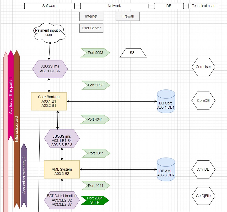
The process is initiated by a user inputting a payment, facilitated by a front-end application and a JMS queue or similar technology that enables front-to-back communication. This step also involves the core banking payment module, which is crucial. If this layer fails, the whole process stalls, and the next step cannot be reached.
The second step involves all the modules that the core banking system calls to complete the payment, for example, the static data.
The third step is the AML check, where another JMS sends the payment for screening. This AML tool, dependent on the OFAC list.Once cleared by the AML system, the payment file is generated by a service from the core banking system.
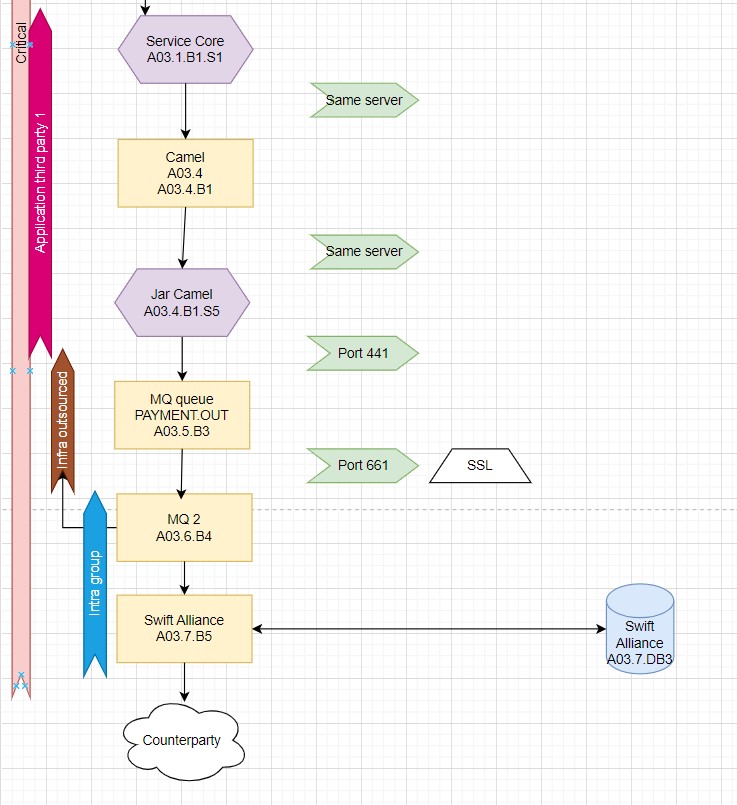
The fourth step involves transferring this file to MQ, there are many software and middleware that can perform this task. In our example, we use Camel.
Once in local MQ, the payment is sent to another MQ managed by Bank headquarters. And the payment is in Swift Alliance eventually.
In total, my Swift Payment process involves three third parties, one intra-group party, eight steps, three SQL databases, and at least eight servers and scripts.
Name Your Elements with a “Risk” Code
It becomes evident that a process can resemble a tangled web, with numerous servers, ports, scripts, middleware, and software involved in completing a business process. To simplify cataloging all dependencies, it’s efficient to use a logic coding system.
Your process needs a codification: for example, Internal Payment as A01, SEPA Payment as A02, and Swift Payment as A03.
Then, code the step of the process, like the core banking payment module as A03.1, and the Payment AML checks as A03.3.
To detail further, add the server where this step occurs after the step code, e.g., A03.3.B2 is on server B2.
This coding, though it might seem odd at first, simplifies the process of identifying the specific scripts executed and the servers involved.
In our example the element A03.3.B2.S7 is the third step of process A03, it is executing script S7 on server B2.
Please find attached our example file:
Create a Diagram
As observed in the first and second sections, mapping all dependencies of a process can be overwhelming. An excel sheet alone won’t talk without a visual representation, which is why a graph should be created. I personally use Draw.io for this purpose. It’s important that your graph:
- Represents all steps of the process
- Includes all third parties involved
- Identifies the technical users needed to perform the business process
The below graph is our humble contribution and might not be exhaustive, but it gives an idea, and we hope it helps the reader.


In conclusion, this article provides a very operational perspective on mapping critical processes. There are countless ways to achieve this, and there is always room for improvement. However, I hope this helps readers define their strategy for fulfilling DORA requirements. Feel free to leave a comment if you have any questions.